Internet Monitoring System ER Diagram

Subscribe our YouTube channel for latest project videos and tutorials Click Here

Posted By freeproject on July 17, 2017
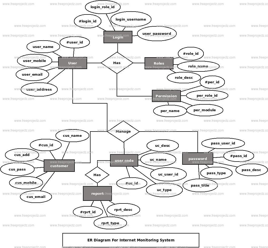
This ER (Entity Relationship) Diagram represents the model of Internet Monitoring System Entity. The entity-relationship diagram of Internet Monitoring System shows all the visual instrument of database tables and the relations between User, Password, Customer, Login etc. It used structure data and to define the relationships between structured data groups of Internet Monitoring System functionalities. The main entities of the Internet Monitoring System are Customer, User, User Code, Password, Report and Login.

Internet Monitoring System entities and their attributes :

  • Customer Entity : Attributes of Customer are customer_id, customer_name, customer_mobile, customer_email, customer_username, customer_password, customer_address
  • User Entity : Attributes of User are user_id, user_name, user_mobile, user_email, user_username, user_password, user_address
  • User Code Entity : Attributes of User Code are user_code_id, user_code_user_id user_code_name, user_code_type, user_code_description
  • Password Entity : Attributes of Password are password_id, password_user_id password_title, password_type, password_description
  • Report Entity : Attributes of Report are report_id, report_name, report_type, report_description
  • Login Entity : Attributes of Login are login_id, login_user_id, login_role_id, login_username, login_password, login_lastlogin

Description of Internet Monitoring System Database :

  • The details of Customer is store into the Customer tables respective with all tables
  • Each entity (Login, User Code, Report, User, Customer) contains primary key and unique keys.
  • The entity User Code, Report has binded with Customer, User entities with foreign key
  • There is one-to-one and one-to-many relationships available between Report, Password, Login, Customer
  • All the entities Customer, Report, User Code, Login are normalized and reduce duplicacy of records
  • We have implemented indexing on each tables of Internet Monitoring System tables for fast query execution.
Internet Monitoring System ER Diagram
Get 6 diagrams only in 300/- or $6.99 USD.
Call or WhatsApp us on +91-8470010001 for more details.

Project Category

Related Entity Relationship Diagram (ERD)

Car Sales System ER Diagram

Car Sales System ER Diagram

This ER (Entity Relationship) Diagram represents the model of Car Sales System Entity. The entity-relationship diagram of Car Sales System shows all the visual instrument of database tables and the relations between Car Models, Inventory, Cars, Booking etc. It used structure data and to define the...
Library Inventory System ER Diagram

Library Inventory System ER Diagram

This ER (Entity Relationship) Diagram represents the model of Library Inventory System Entity. The entity-relationship diagram of Library Inventory System shows all the visual instrument of database tables and the relations between Store, Author, Student, Address etc. It used structure data and to...
Job Portal System ER Diagram

Job Portal System ER Diagram

This ER (Entity Relationship) Diagram represents the model of Job Portal System Entity. The entity-relationship diagram of Job Portal System shows all the visual instrument of database tables and the relations between Registration, Interview, Employee, Call Letter etc. It used structure data and to...
Online Crime Investigation  ER Diagram

Online Crime Investigation ER Diagram

This ER (Entity Relationship) Diagram represents the model of Online Crime Investigation Entity. The entity-relationship diagram of Online Crime Investigation shows all the visual instrument of database tables and the relations between Criminal , Department , Case , FIR etc. It used structure data...
Contractor Management System ER Diagram

Contractor Management System ER Diagram

This ER (Entity Relationship) Diagram represents the model of Contractor Management System Entity. The entity-relationship diagram of Contractor Management System shows all the visual instrument of database tables and the relations between Company, Timesheet, Contract, Salary etc. It used structure...
Car Parking System ER Diagram

Car Parking System ER Diagram

This ER (Entity Relationship) Diagram represents the model of Car Parking System Entity. The entity-relationship diagram of Car Parking System shows all the visual instrument of database tables and the relations between Parking, Parking Space, Car, Car Owner etc. It used structure data and to...
Blogging System ER Diagram

Blogging System ER Diagram

This ER (Entity Relationship) Diagram represents the model of Blogging System Entity. The entity-relationship diagram of Blogging System shows all the visual instrument of database tables and the relations between Blog Category, Blog Type, Blog, Technology Blog etc. It used structure data and to...
Mobile Service Enqiry System ER Diagram

Mobile Service Enqiry System ER Diagram

This ER (Entity Relationship) Diagram represents the model of Mobile Service Enqiry System Entity. The entity-relationship diagram of Mobile Service Enqiry System shows all the visual instrument of database tables and the relations between Customer, Payments, Mobile, Service etc. It used structure...
Reseller Management System  ER Diagram

Reseller Management System ER Diagram

This ER (Entity Relationship) Diagram represents the model of Reseller Management System Entity. The entity-relationship diagram of Reseller Management System shows all the visual instrument of database tables and the relations between Order, Company, Reseller, Company Type etc. It used structure...
Ecare System ER Diagram

Ecare System ER Diagram

This ER (Entity Relationship) Diagram represents the model of Ecare System Entity. The entity-relationship diagram of Ecare System shows all the visual instrument of database tables and the relations between Organization, Logins, Customer, Invetories etc. It used structure data and to define the...
Call FreeProjectz WhatsApp FreeProjectz